Inputs and outputs
IOLogic CAN I/O Module
Eight inputs and eight outputs on one sealed plug, with the same connector and pinout as the Holley CAN I/O module.
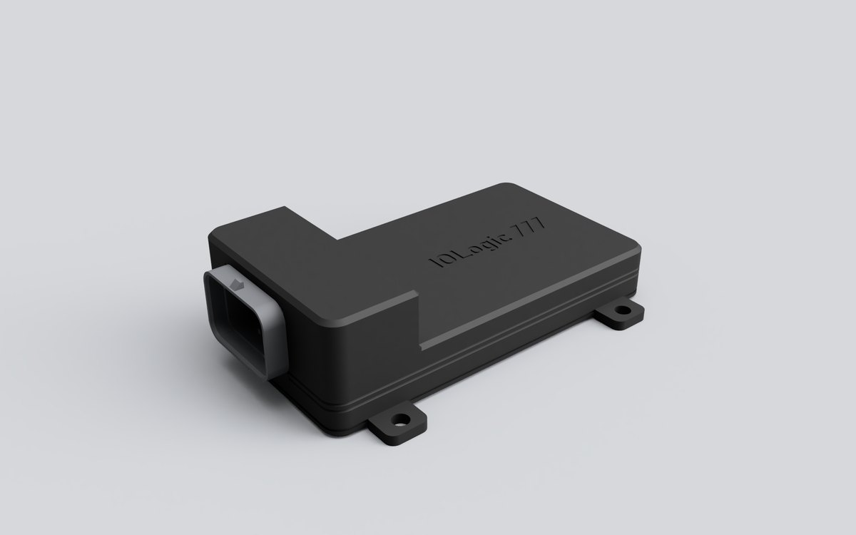
IOLogic enclosure with its 34-position connector.
What it does
- One 34-position connector, so a Holley 554-165 or 554-166 harness plugs straight in.
- Eight inputs tolerate 12 V: 0–5 V sensors, +12 V or ground switched signals and thermistors, with frequency on inputs 1–6.
- Eight low-side outputs with on/off and PWM control.
- CAN serial number can be changed over USB.
Specifications
| Connector | TE Superseal 1.0, 34-position |
|---|---|
| Inputs | 8, 12 V tolerant, switched pull-ups |
| Outputs | 8 low-side, protected solid-state switches |
| Processor | Microcontroller with dedicated CAN controller |
| Enclosure | 127.8 × 69.8 × 37.9 mm with 4 screw tabs |
Pinout
PowerGroundCAN HCAN LInputOutput
Main connector
TE Superseal 1.0, 34-position. Looking into the connector on the module, with the lock at the top.
- 1Switched ignition 12 V
- 2Output 2
- 3Output 1
- 4Ground
- 55 V sensor power
- 6Output 4
- 75 V sensor power
- 8Sensor ground
- 9Output 3
- 105 V sensor power
- 11CAN H
- 12Sensor ground
- 13Input 1
- 14Input 2
- 15Input 3
- 16Input 4
- 17Ground
- 18Ground
- 19CAN L
- 20Sensor ground
- 21Input 5
- 22Input 6
- 23Input 7
- 24Input 8
- 25Ground
- 26Output 5
- 27Module ground
- 285 V sensor power
- 29Output 6
- 30Sensor ground
- 31Output 7
- 325 V sensor power
- 33Sensor ground
- 34Output 8
Not to scale. Check the numbers molded on the connector before wiring. Pin colors only show each pin's function. They don't reflect the actual wire colors of any included pigtail.
Before you buy
- 20 V analog sensors aren't supported: they read clipped at 5 V.
- Input protection doesn't cover spikes above about 40 V.